Traffic Signals - Yarger Engineering, Inc. 317-475-1100 Email Us
- Pretimed Signals
- Actuated Signals
- Turn Arrows
- Controller
- Signal Coordination / Progression
- Signal Indications / Heads
- Traffic Signal Costs
- Manual on Uniform Traffic Control Devices (MUTCD)
- Traffic Signal Warrant Studies
Traffic signals are devices that control and hopefully optimize traffic flow through an intersection. They work by dividing up the time allowed to different movements in an intersection. Initially, this was done by a policeman standing in the middle of the intersection directing traffic, and occasionally still is today. Modern traffic signals are basically divided into to two types, pretimed and actuated.

Pretimed Signals
Pretimed signals work on a clock basis and assign a predetermined amount of green, yellow and red to various vehicle movements; and walk, flashing don’t walk, and solid don’t walk to pedestrians. These predetermined amounts of time, or timings, are the same for many iterations called cycles where the same pattern repeats over and over until another pattern is called by a clock. Pretimed cycles usually last between 60 and 120 seconds, but can be lower or higher
Actuated Signals
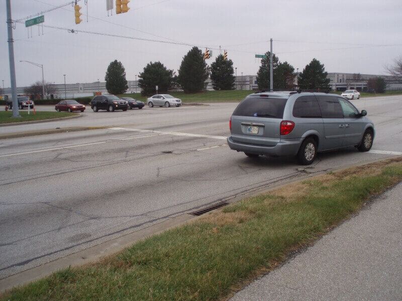
Actuated signals work by sensing vehicles on the road or pedestrians at the crosswalk and adjusting the amount of green time. Notice the octagon shapes cut into the pavement right behind the minivan. These are loop detectors. The amount of yellow, all red, and flashing don’t walk are still fixed in an actuated signal. The walk can be fixed or vary depending on the settings in the traffic controller.
Turn Arrows
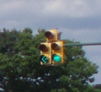
Turn arrows are used to help address congestion and safety concerns when a “two phase” (north and south greens together then east and west greens together without any arrows) won’t work. Adding arrows or phases can help address congestion during peak times, but also add delay during off-peak times. They almost always increase the required cycle length which increases delay, especially on the side street and in the turn lanes with protected arrows (3 sections, no green or yellow balls).
Controller
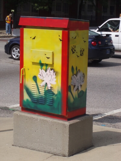
The traffic controller is inside the metal box on the street corner. The boxes come in different sizes, shapes and colors, but they typically are about five to six feet tall, metal finished, yellow or black. In some cases they may be painted other colors… Inside the box are various devices, but the main devices are:
- traffic controller
- detector amplifiers
- load switches
- malfunction monitoring unit
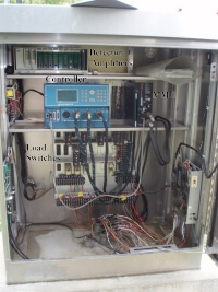
The traffic controller is the brains of the unit and takes various inputs and turns them in to the colored lights we see. As mentioned before, they can be pretimed in which case the inputs are the various time settings along with a schedule. The Actuated controller will use both preprogrammed inputs and the detector inputs to develop the actual green times. Either type can received information from another controller called a master controller that synchronizes nearby signals so that all run the same cycle length and are a specific “offset” of time apart from the start of green at one signal to the start of green of the next signal.
The detector usually has two parts, the sensor in or near the road, and the amplifier or other unit in the controller box. The sensor can be loop detectors in the road made of wires forming an electromagnet and the amplifier senses the change of current in the electromagnet when a vehicle passes over. See the photo above with the minivan. Another common type are video sensors where a camera is placed over the intersection and the main detector unit sees when the pixels change. Both have pros and cons, and there are several others, but generally they work by sensing the presence of vehicles in a predefined area and adjusting the signal green timings accordingly.
As you can imagine, this gets a bit complex when trying to run actuated signals in coordination. There is a third type of signal, semi-actuated, which is really a hybrid of the two where the side streets and turn lanes are actuated, but the main street is not. See “Fully Actuated versus Semi-Actuated Traffic Signal Systems Research”, a paper written by Mr. Yarger for a much more detailed discussion.
Load switches are basically relays that turn the low voltage controller outputs into the higher voltage outputs for the lights we see.
The Malfunction Monitor Unit’s (MMU) job is to watch over the controller and the load switches and stop catastrophic problems, like a northbound and eastbound green being on at the same time. When the malfunction monitor unit senses this, it will typically send the traffic signal into a predetermined flash pattern within a fraction of a second and remain that way until the controller is reset. They also record what happened in the controller so that the technician knows where to start looking for the problem.
Signal Synchronization/Progression
Signal synchronization (progression) in most real world situations is much more difficult to achieve than may be first thought. One-way progression is fairly easy. Two-way progression becomes much harder since if the signalized intersections are 15 seconds apart and there is 30 second of green at each signal, then if the signals are progressed eastbound, the eastern signal will turn green 15 seconds after the western signal. The westbound traffic will arrive at the west signal just when it is turning red. If the signals start green together, then there will be only 15 seconds of green left at the second signal in both directions. Those in the back of the pack (platoon) that needed 20 or 30 seconds of green will have to wait until the next time the signal turns green. This becomes even harder with turn arrows, pedestrians and a downtown grid pattern where the signals would need to be progressed in four directions!
Signal Indications
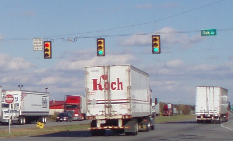
The placement of the signal indications (heads) is regulated by the Manual on Uniform Traffic Control Devices and local standards, but generally two indications should be between 40 and 150 feet beyond the stop line and within 20 degrees left or right of the view of the approaching vehicles. Additional indications can be placed outside of this area at the discretions of the design engineer, such as on the far left signal pole for a left turn indication or over the stop line when the far side heads may be too far away.
The size of the indications is usually 12” in diameter, but 8” lenses are allowed under certain circumstances. Newer ones are made of LED lights which has dropped the power consumption considerably over the old incandescent lights. Lately the Indiana DOT has been using more and more back plates on their signal indications with a reflective strip to help them be seen in bright daylight or at night.
The placement of the signal indications (heads) is regulated by the Manual on Uniform Traffic Control Devices and local standards, but generally two indications should be between 40 and 150 feet beyond the stop line and within 20 degrees left or right of the view of the approaching vehicles. Additional indications can be placed outside of this area at the discretions of the design engineer, such as on the far left signal pole for a left turn indication or over the stop line when the far side heads may be too far away. The size of the indications is usually 12” in diameter, but 8” lenses are allowed under certain circumstances. Newer ones are made of LED lights which has dropped the power consumption considerably over the old incandescent lights.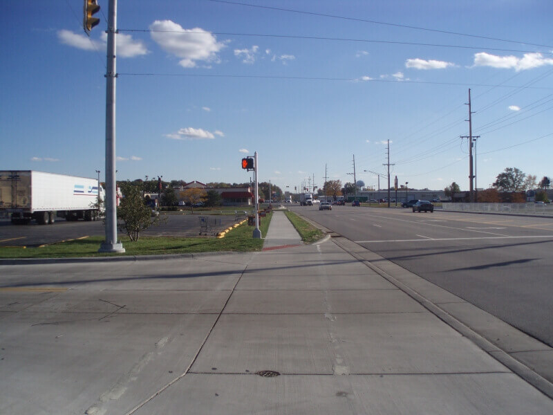
Signal Poles
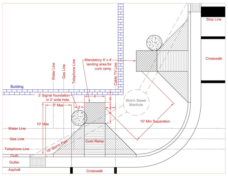
Placement of the poles is a bit more complex than it may first appear due to safety and access requirements. On high speed facilities the poles should be far away from the road so as not to become a hazard to a vehicle that leaves the road. Poles with pedestrian indications and buttons need to be placed conveniently for the pedestrians to use, including the blind and those in wheelchairs. For the blind, some pedestrian buttons talk, other make noises and even vibrate. These are called accessible pedestrian signals (APS). In the photo to the right the main signal pole was placed away from the road while a pedestrian signal pole with a breakaway base was placed adjacent to the sidewalk so pedestrians could reach the pushbutton and easily see the pedestrian indication. The poles in this case were placed with the intention of receiving APS signals in the future. Notice that the pedestrian indication is placed on the far side of the pole from the street so that if a semi-trailer were to cut the corner, the indication is about two feet farther from the street. Where pole placement becomes the most complicated is in urban environments where there is still a safety concern of vehicles leaving the road and hitting a pole, but there are also blind pedestrians that need accessible pedestrian signals and curb ramps for wheelchairs and others that can’t negotiate curbs. The APS buttons need to be close to the crosswalk, but no closer together than 10’ so as not to be confusing when talking or making other sounds. They also should be close to the street to be crossed, but not in the grade of the curb ramp. To add to the complexity, there are often underground utilities and other conflicts, such as basements under the sidewalks or permanently mounted street furniture (benches, trashcans, mailboxes, planting strips). Of course, the poles must also be placed so that the signal indications are in the right location. See the figure below for trying to place a round peg (foundation) in a square hole in the utilities and other constraints.
Traffic Signal Costs

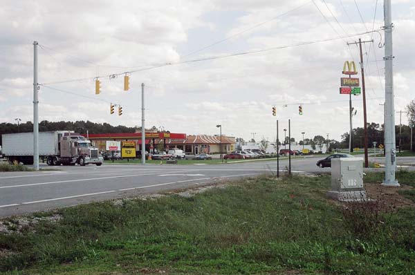
Traffic signals can vary in cost from about $75,000 to $150,000 per signal excluding other improvements to the intersection, such as turn lanes, sidewalks, curb ramps, utility relocations or purchasing right-of-way. There is also the ongoing maintenance and operating (electricity) costs. The electrical consumption has drop with the use of LED, but the power bill still has to be paid. Note the meter on the right pole in the photo at the top of the page.
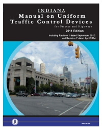
Manual on Uniform Traffic Control Devices
Traffic signals are regulated by the Manual on Uniform Traffic Control Devices (MUTCD) which controls where and when they may be installed and how they are designed and operate. Each state has its own version or adopts the federal version. See Indiana MUTCD or Federal MUTCD.
Trafic Signal Warrant Studies
The Indiana MUTCD contains nine specific warrants for when a traffic signal is allowed to be installed. Other states may have more or less.
- Eight-Hour Vehicle Volume
- Four-Hour Vehicle Volume
- Peak Hour
- Pedestrian Volume
- School Crossing
- Coordinated Signal System
- Crash Experience
- Roadway Network
- Intersection Near A Grade Crossing
Call us at 317-475-1100 or email us today!
